


What Is Electrical Principle?
Electrical Principle
The most core component of an electric vehicle is the battery system, and one of the most core aspects of the battery system is its electrical principle. The architecture design of the electrical principle is premised on meeting the requirements put forward by the vehicle design for the battery system, and once the design is finalized, it determines the functions of the battery system. This chapter will cover some knowledge about the electrical principles of the battery system.
Electrical Configuration
The requirement for the battery system's electrical configuration stems from the battery system's requirements. To summarize the vehicle's requirement for the battery system in one simple sentence: to safely and controllably provide electrical energy for the electric vehicle. The three key words in this sentence are electrical energy, controllable, and safe. Electrical energy refers to the components within the battery system, such as battery modules, that can provide electrical energy. Controllable refers to the components within the battery system, such as the Battery Control Unit (BCU), contactors or relays, and current/voltage sensors, that can control the current. Safe refers to the components within the battery system that are related to system safety, such as fuses and Manual Service Disconnect (MSD). Figure 9-1 shows a simple electrical configuration of a battery system, including the three types of components mentioned above. These include components such as battery modules, Battery Control Unit (BCU), main positive contactor, main negative contactor, fast charge positive contactor, fast charge negative contactor, pre-charge relay, pre-charge resistor, current sensor, and Manual Service Disconnect (MSD) with a fuse.
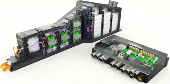
As seen in Figure 9-1, the battery system consists of 1 Master Control Board, several Slave Control Boards, 1 MSD, several cells, high-voltage relays, low-voltage wiring harnesses, and various connectors. The Master Control Board is responsible for functions such as high-voltage relay logic control, total voltage acquisition, high-voltage connector and MSD connection status monitoring, current acquisition, charging control, vehicle communication, slave board information collection, fault diagnosis, and program upgrade. Each Slave Control Board is configured to acquire cell voltage (0~5V) and is equipped with temperature sensors distributed across each battery module in the box.
The battery system in Figure 9-1 is relatively simple and does not yet include subsystems such as the water cooling system, heating system, and temperature control system.
Electrical Principles
Figure 9-2 shows an electrical principle of a battery system. As can be seen from the figure, the battery pack integrates positive and negative contactors, pre-charge resistors, pre-charge relays, MSD, battery management system, and current sensors. The contactors inside the fast/slow charger and the lithium battery pack are controlled by the Battery Management System (BMS), and positive logic is recommended. The positive and negative contactors are equipped with auxiliary contacts, and the feedback signal is sent back to the battery management system.
The pre-charge circuit pre-charges the vehicle's high-voltage system, and the pre-charge voltage is the system voltage. The power supply of the main board of the battery management system should have ON power, live wire and charging wake-up interface. It is activated by ON power during normal operation and activated by an external charging power source during charging. The battery management system should have insulation resistance detection and busbar voltage and current detection functions. Current detection can adopt shunt or Hall current sensors. The battery management system should have corresponding strategies for insulation resistance and fault handling. The insulation resistance detection requirements are detailed in the corresponding requirements of the battery design input sheet. The main board of the battery management system should be able to detect the charging control and confirmation signals CC/CP/CC2 that meet the national charging standards. AC charging methods should be designed according to the typical control pilot circuit principle of Charging Mode 3 Connection Method B in the national standard, allowing AC charging through a household 16A socket and an AC charging pile. A maintenance switch and a high-voltage fuse should be located in the middle of the power battery pack. If the battery pack is a split-box system, it is recommended to install a maintenance switch and a high-voltage fuse in the electrical middle position of each box. The high-voltage connector between the MSD and the connection cable should form an interlock circuit within the battery pack, and the interlock signal is detected by the battery management system. The high-voltage connector for the total voltage and total negative output of the power battery pack uses pre-set connectors, and the high-voltage interlock control signal forming a resistance loop with the Power Control Unit (PCU) and the motor is detected by the Vehicle Control Unit (VCU).

The battery management system adopts a master-slave architecture. The communication between the Master Control Board and the Slave Control Boards is via the CAN bus. Figure 9-3 shows the internal CAN bus structure of the battery system.

As can be seen from Figure 9-3, each module is equipped with a Slave Control Board. The Slave Control Board is integrated with the module, allowing for flexible configuration, scalability, and the creation of standardized modules to meet platform requirements. The electrical design mainly focuses on the high-voltage circuit design of the battery pack, including the development aspects of high-voltage electrical safety, pre-charge circuit, high-voltage cable selection, MSD, and current sensors.


